

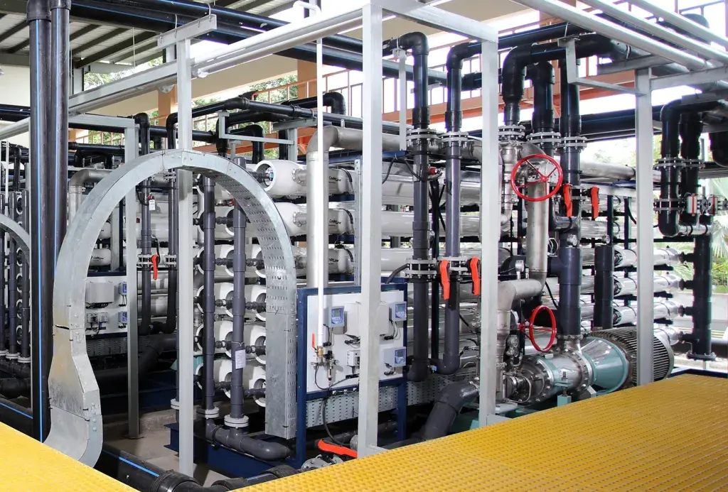
RO membrane CIP should start from normalized performance trends, not raw permeate flow. First exclude temperature, salinity, recovery, instrumentation, valve, and pretreatment changes; then connect the pattern in normalized flow, salt passage, and pressure drop to deposit evidence before selecting the cleaner, sequence, pH, temperature, and contact time permitted by the membrane OEM.
When an RO membrane needs CIP
Use a baseline collected while the membranes are clean and operation is stable. DuPont’s February 2026 FilmTec manual recommends cleaning when one or more of these conditions occur: normalized permeate flow drops 10%, normalized salt passage increases 5–10%, or normalized pressure drop increases 10–15%. It also warns that lower feedwater temperature can reduce flux without indicating fouling.
The figures come from the FilmTec Reverse Osmosis/Nanofiltration Membranes Technical Manual, Form No. 45-D01504-en Rev. 19. Apply the correct OEM limits for the installed membrane; do not combine thresholds from a different brand or model without technical approval.
| Normalized indicator | FilmTec 2026 screening trigger | What to check before CIP |
|---|---|---|
| Permeate flow | Down 10% | Temperature, pressure, recovery, feed salinity, flowmeter, valves, cartridge filter, and pretreatment |
| Salt passage | Up 5–10% | Conductivity calibration, temperature, O-rings/interconnectors, telescoping, oxidant exposure, and pressure-vessel pattern |
| Feed-to-concentrate pressure drop | Up 10–15% | The affected stage, spacer blockage, debris, biofilm, solids carryover, valves, and actual flow |
Do not wait for all three indicators to move. Delayed cleaning can make deposits harder to remove, while repeated CIP without diagnosis adds chemical exposure and waste and may conceal a pretreatment failure.
Diagnostic map from symptoms to foulant
One symptom does not identify one foulant. Combine stage-by-stage trends with water analysis, deposit examination or autopsy, SDI/turbidity, antiscalant and biocide history, and process changes.
| Operating pattern | Cause to test | Distinguishing evidence | Initial cleaning direction |
|---|---|---|---|
| Pressure drop rises first in stage one | Suspended solids, biofilm, cartridge breakthrough, debris | SDI/turbidity, cartridge differential pressure, ATP/microbiology, slimy deposit, inlet inspection | OEM-approved high-pH or biocleaning when organics/biofilm are proven; correct pretreatment |
| Normalized flow falls while pressure drop is fairly stable | Scale, organic adsorption, compaction, pretreatment change | Ion balance, scaling projection, deposit analysis, feed temperature/pressure history | Low-pH for compatible inorganic deposits or high-pH for organics, based on evidence |
| Salt passage rises sharply without a fouling pattern | O-ring leak, membrane damage, oxidation, telescoping, instrument error | Vessel probing, vessel permeate conductivity, chlorine/oxidant history, element inspection | Do not rely on CIP; repair the leak/damage and consult the OEM |
| White/crystalline deposit and changed scaling projection | Carbonate or mineral scale; distinguish silica and sulfate scale | Deposit analysis, calcium, alkalinity, sulfate, silica, barium/strontium, pH, recovery | Low-pH cleaner only for compatible deposits; some scales need a specialist procedure |
| Brown/red deposit | Iron or corrosion products | Total/dissolved iron, source corrosion, oxidation point, deposit analysis | Membrane-approved metal-deposit cleaner; remove the iron carryover source |
| Slime, odour, or rapid regrowth | Biofilm and organic nutrients | Site ATP/HPC method, TOC, microscopy where justified, sanitation/biocide history | Compatible high-pH/biocleaning, followed by microbiological and dead-leg control |
| Oil/grease or organic breakthrough | Hydrocarbon, surfactant, process leak, carbon breakthrough | Oil and grease/TOC, process SDS, carbon-bed change, deposit sample | Suitable high-pH cleaner; isolate the source and verify material compatibility |
PT Beta Pramesti Asia supplies industrial RO and UF membrane cleaners: BETAGARD 6510 for inorganic deposits suited to low-pH cleaning, and BETAGARD 6520 for organic contamination, oil, grease, and biofilm suited to high-pH cleaning. Selection still requires the membrane model, deposit evidence, and OEM limits.
Set the cleaning sequence without damaging the membrane
Do not choose the sequence from a rule that acid or alkaline cleaner must always go first. With mixed foulants, the wrong cleaner can make a deposit harder to remove. Set the sequence from deposit analysis, process history, the OEM manual, product compatibility data, and a laboratory test when the risk justifies it.
| Decision | Mandatory question | Hold condition |
|---|---|---|
| Low-pH cleaner | Is the deposit a carbonate/metal scale that this cleaner can dissolve? | Membrane, elastomer, coating, or scale is incompatible; deposit remains unidentified |
| High-pH cleaner | Are organics, oil, or biofilm dominant? | Process chemical may react, pH/temperature exceeds OEM limits, or disposal is not ready |
| Two-stage cleaning | Is a mixed deposit proven, and will each stage be fully flushed? | Sequence is unapproved, pH is uncontrolled, or first-stage waste will contaminate the tank |
| Sanitation/disinfection | Does the membrane permit the agent, concentration, pH, temperature, and exposure time? | Oxidation history is unknown or the OEM prohibits the selected agent |
Never mix acid cleaner with alkaline cleaner, hypochlorite, bisulfite, or another chemical unless the manufacturer’s written procedure explicitly permits it. Review the SDS and provide chemical-resistant PPE, ventilation, eyewash/shower, secondary containment, and lockout-tagout. Verify compatibility of tanks, hoses, pump, seals, cartridges, instruments, pressure vessels, membranes, interconnectors, and adhesives.
An auditable CIP procedure
Flow, pressure, concentration, pH, temperature, and circulation time must follow the installed membrane model and cleaner instructions. The steps below define control points, not a universal recipe.
- Freeze the baseline. Save feed/permeate/concentrate flow, stage pressures, conductivity, temperature, recovery, normalized performance, and alarms before shutdown.
- Confirm the cause. Review pretreatment, cartridge filters, antiscalant/dosing, oxidant, valves, instrument calibration, and feedwater changes. Retain a deposit sample where practical.
- Isolate safely. Stop production, depressurize, lock out, and separate the product/permeate tank from chemical return as defined by the P&ID.
- Prepare a clean loop. Clean the CIP tank, hoses, strainer, and piping. Use permeate or OEM-specified water so the cleaner does not react immediately with makeup-water hardness or contamination.
- Prepare the solution to procedure. Mix correctly and record batch volume, lot, active strength where relevant, pH, temperature, and operator. Stay inside membrane limits.
- Displace at low flow. Send process water to the approved waste route until cleaning solution reaches the return. The dirtiest first return should not automatically go back to the tank.
- Circulate at low pressure. Avoid significant permeate production and telescoping. Trend pH, temperature, colour/turbidity, foam, pressure drop, and strength; adjust only as the procedure allows.
- Soak and recirculate if permitted. OEM/product instructions control duration and cycles. Replace a saturated or heavily contaminated solution instead of redepositing foulant.
- Flush completely between stages. Drain to the approved route and flush until pH, conductivity, colour, and residual meet the procedure before the next cleaner or restart.
- Restart gradually. Operate safely, route initial permeate as specified, inspect for leakage, and stabilize temperature, recovery, and flow before judging normalized results.
Chemical-metering dosing pumps support online treatment but do not replace a CIP pump sized for circulation flow, material compatibility, and low-pressure duty. For membrane or pressure-vessel component replacement, review RO membranes and components from Watermart.
Post-CIP acceptance criteria
CIP success is not a higher raw flow at a different temperature. Compare stabilized normalized data with the agreed clean baseline, then verify that the original cause is controlled.
| Criterion | Acceptance evidence | Escalation sign |
|---|---|---|
| Mechanical integrity | No leak, abnormal vibration, telescoping indication, or vessel anomaly | Leakage, high vessel permeate conductivity, or inspection damage |
| Normalized permeate flow | Recovers toward a realistic baseline and remains stable | No change or a rapid repeat decline |
| Normalized salt passage/rejection | Returns to its control envelope after flushing/stabilization | Remains high: investigate O-rings, damage, oxidation, or channeling |
| Stage pressure drop | Falls and stabilizes within the OEM limit | One stage remains high: blockage/deposit may remain |
| Cleaning residual | pH, conductivity, colour, foam, and residual meet release criteria | Cleaner carries into permeate or the downstream process |
| Pretreatment control | SDI/turbidity, cartridge DP, antiscalant, dechlorination, and biocontrol are stable | Root cause remains and refouling will recur |
Define acceptance before cleaning: comparison baseline, normalization conditions, stabilization period, sample points, instruments, and release authority. Forcing an aged membrane back to its original commissioning value may be unrealistic; accepting a small recovery without explaining damage or residual fouling is equally weak.
When performance does not recover
Stop repeating the same recipe. Confirm active concentration, pH, temperature, vessel flow, contact time, and whether solution reached every stage. Investigate a wrong foulant diagnosis, saturated cleaner, CIP-loop channeling, compaction, oxidation, abrasion, O-ring leakage, telescoping, brine seals, and pressure damage.
Use vessel/element probing, deposit analysis, or membrane autopsy when the value of lost production supports it. Feed the findings back into pretreatment, recovery, antiscalant, dechlorination, cleaning triggers, and shutdown preservation rather than simply cleaning more often.
Data package for a CIP review
Provide membrane model, quantity, age, and array; P&ID; design projection; stage feed/permeate/concentrate flow and pressure; temperature, conductivity, pH, recovery, and normalized trends; complete water analysis; SDI/turbidity; pretreatment and cartridge logs; every chemical, dose, point, and SDS; oxidant history; deposit sample/photos; all CIP records; and the disposal route.
Never assume spent cleaner is suitable for direct discharge. Assess pH, metals, organics, salinity, and active ingredients against the site’s treatment system and environmental approval. Indonesia’s Government Regulation No. 22 of 2021 covers water-quality protection and waste management; sector and location requirements still control final handling.
These inputs let the team distinguish a valid cleaning need from repair, element replacement, or correction of the reverse-osmosis chemical program and RO membrane maintenance program.