

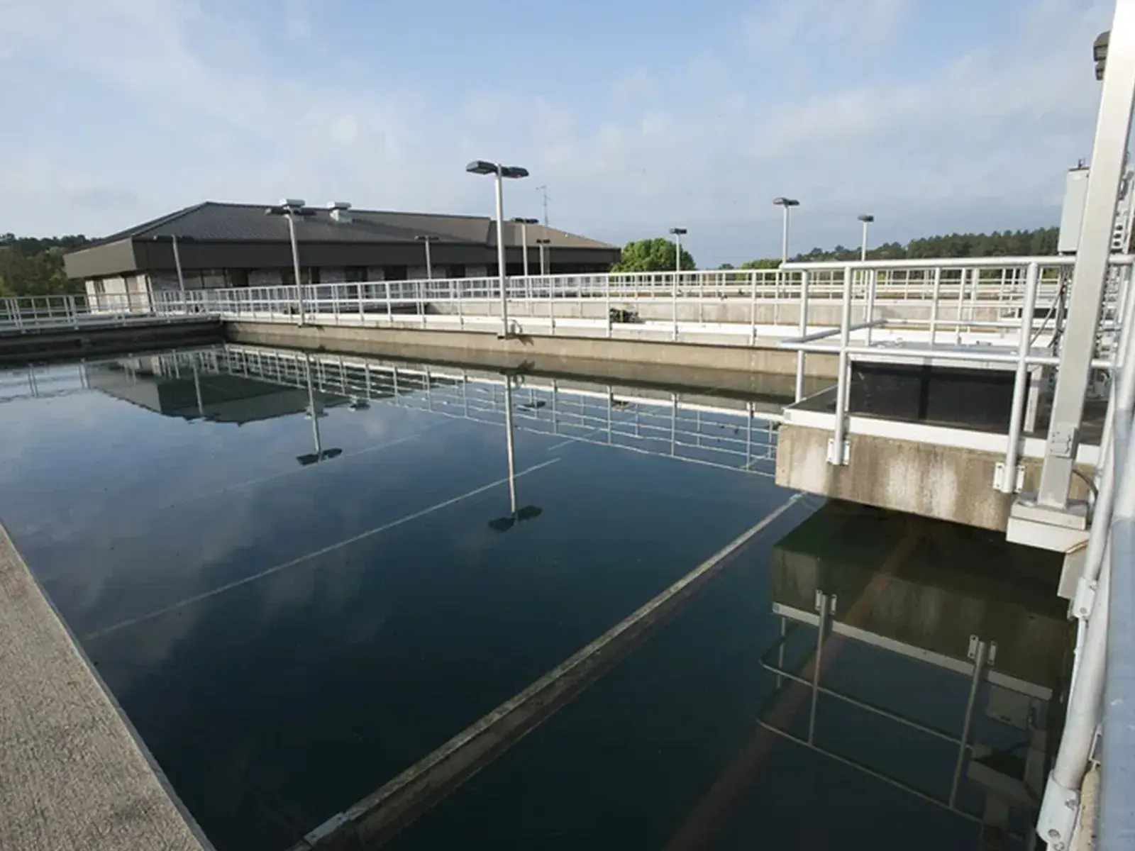
Dissolved air flotation (DAF) sizing cannot rely on average flow alone. Combine actual peak flow, pressurized recycle, TSS and oil loading, chemical response, and skimmer sludge duty. Surface area can be screened from hydraulic loading, but final selection requires representative influent data, jar testing, and, for high-risk duties, a pilot with actual wastewater.
Minimum data required before sizing a DAF
Use hourly or batch data that captures normal operation, peaks, CIP events, product changeovers, rainfall, and process upsets. A daily composite alone can hide short peaks that control equalization, chemical contact-tank, and DAF capacity.
| Design input | Units and statistics required | Selection impact |
|---|---|---|
| DAF influent flow | m³/h: average, one-hour peak, peak duration, batch volume | Establishes hydraulic duty and equalization requirement |
| TSS | mg/L: median, P90, representative maximum | Changes solids loading, air demand, and sludge production |
| FOG/oil and grease | mg/L; distinguish free oil from emulsified oil | Determines coagulation, pH, and upstream separation needs |
| COD/BOD | mg/L and dissolved fraction where available | Shows what DAF can remove and what remains for biological treatment |
| pH, temperature, alkalinity, conductivity | Range and shift variation | Affects coagulation, air solubility, materials, and pH control |
| Existing chemicals | Product, dose, injection point, contact time | Avoids incompatibility and frames the jar-test program |
| Effluent target | TSS, FOG, COD and downstream process needs | Defines performance that must be demonstrated, not assumed |
| Sludge | Flow, % total solids, sticky/fibrous behavior, discharge hours | Sizes storage, skimmer, pumps, and dewatering |
DAF sizing from design flow to effective area
Start with design Q, the maximum flow that must be treated after equalization. Do not use the upstream pump nameplate without checking level trends and batch behavior. In a recycle system, check separation area against total flow entering the flotation zone:
Total Q = influent Q + recycle Q
Effective area A = total Q ÷ hydraulic loading rate
U.S. EPA design material identifies hydraulic loading and air-to-solids ratio as key DAF parameters. Pilot studies summarized by EPA reported maximum hydraulic loading around 81.5–101.8 L/min/m², equivalent to 4.9–6.1 m³/m²/h; another EPA manual used 1.36 L/s/m², about 4.9 m³/m²/h, including 50% recycle as its case-design basis. These historical values are useful screening references, not a guarantee for every wastewater (U.S. EPA pond systems design manual; U.S. EPA Treatability Manual).
Worked screening example for 40 m³/h
Assume equalization limits DAF influent to 40 m³/h and initial testing uses 25% recycle, giving 10 m³/h recycle. At a screening hydraulic loading of 5 m³/m²/h:
A = (40 + 10) ÷ 5 = 10 m² effective area.
This is not yet a purchase size. The engineer must still check inlet distribution, contact zone, short-circuiting, sludge freeboard, float storage time, skimmer space, settled-solids hopper, redundancy, turndown, and net effective area after baffles.
Check solids, oil, recycle, and air loading
Influent TSS load is kg/h = Q (m³/h) × TSS (mg/L) ÷ 1,000. At 40 m³/h and 1,200 mg/L TSS, the load is 48 kg/h before chemical addition. Add the mass of chemical precipitates and other generated solids; never size the skimmer from raw TSS alone.
Recycle ratio is recycle Q ÷ influent Q × 100%. More recycle can deliver more air-saturated water, but it also raises hydraulic and energy loading. EPA material documents designs and tests with widely different recycle rates and air-to-solids ratios around 0.005–0.1 in particular applications. Because industrial wastewaters vary, saturator pressure, recycle, and air-to-solids ratio should be confirmed from vendor data, relevant flotation testing, and a pilot where emulsions or solids loading are uncertain (U.S. EPA development document).
| Check | Too low | Too high |
|---|---|---|
| Recycle/dissolved air | Floc does not rise, cloudy effluent, settling solids | Turbulence, floc shear, higher hydraulic load and energy |
| Coagulant dose | Stable emulsion or colloids remain | More sludge, pH shift, higher cost and residual carryover |
| Polymer dose | Fragile or undersized floc | Sticky floc that disrupts skimming and dewatering |
| Skimmer speed | Float accumulates and remixes | Sludge becomes dilute and handling volume rises |
| Float depth/age | Insufficient drainage time | Odor, bridging, aged float, and higher mechanical load |
Jar and flotation tests before equipment selection
A DAF jar test must evaluate bubble-assisted separation; good settling does not automatically predict good flotation. Use fresh samples at process temperature, then vary pH, coagulant type and dose, polymer addition point, rapid-mix energy, flocculation time, and polymer dose. Record TSS, FOG, dissolved/total COD where relevant, float volume, rise velocity, subnatant clarity, and floc resistance to recycle shear.
- Run an untreated blank to observe free oil and inherently floatable solids.
- Test a pH and coagulant-dose range, not a single recipe.
- Add polymer after coagulation with mixing energy that preserves floc.
- Simulate pressurized recycle or use a bench flotation cell that represents DAF behavior.
- Repeat on normal and peak-load samples; record temperature and sample age.
- Select conditions on both effluent quality and sludge behavior, not maximum removal alone.
PT Beta Pramesti Asia supplies wastewater-treatment coagulants and flocculants for floc formation, but final dose must come from testing the actual wastewater. If the package requires separate chemical-metering hardware, Watermart’s water-treatment dosing pumps are a relevant equipment handoff.
Skimmer, sludge, and commissioning checklist
The skimmer must remove peak float loading without dragging excessive water. Check flight material, cleaning access, drive torque, speed control, beach/ramp position, and response to sticky float. Provide a hopper for grit or non-floating solids when the wastewater requires it.
During commissioning, verify influent/recycle flow, saturator pressure, microbubble release pattern, pH, actual chemical dose, water level, skimmer speed, influent-effluent TSS/FOG, sludge volume and percent solids, and energy use. Configure alarms for pressure loss, abnormal level, recycle-pump trip, and high skimmer torque.
Float sludge needs its own handling route. Collect daily volume, % total solids, density, foaming tendency, and polymer response before choosing a Betaqua Screw Press for dewatering or another method. Do not assume DAF sludge behaves like biological sludge.
Vendor data sheet for DAF selection
Send the following package so the vendor can separate assumptions from measured data:
- industry and wastewater source by stream;
- process flow diagram, operating hours, average/peak flow, peak duration, and batch volume;
- dated laboratory results for TSS, FOG, COD/BOD, pH, temperature, alkalinity, conductivity, and corrosive constituents;
- effluent targets and the process downstream of the DAF;
- complete jar/flotation-test results with chemicals, doses, and float photographs;
- footprint and elevation limits, required material, electrical supply, air, service water, and hazardous-area classification;
- duty/standby, turndown, automation, remote monitoring, and chemical-storage requirements;
- sludge data and the storage, pumping, and dewatering method;
- sampling, performance-test, documentation, training, and spare-parts requirements.
With these inputs, the team can evaluate a Dissolved Air Flotation (DAF) unit as one system covering hydraulic loading, solids loading, recycle, chemistry, and sludge handling—not merely choose a catalog’s nominal flow rating.